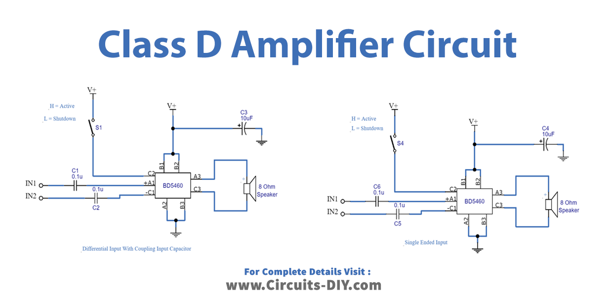
Simple Class D Amplifier Circuit
Bias Vcc Class AB amplifier uses linear regulating transistors to modulate output voltage. η = 30% at temp rise test condition. How a Class D Amplifier Works Feed back Triangle +VCC Nch Level Shift Error Amp COMP Dead Time Nch -VCC Class D amplifier uses MOSFETs that are either ON or OFF.
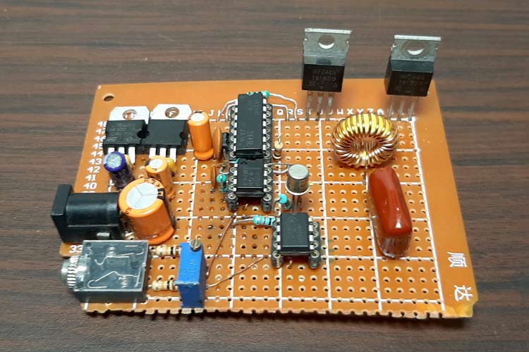
Insider High Power Class D Amplifier Schematic
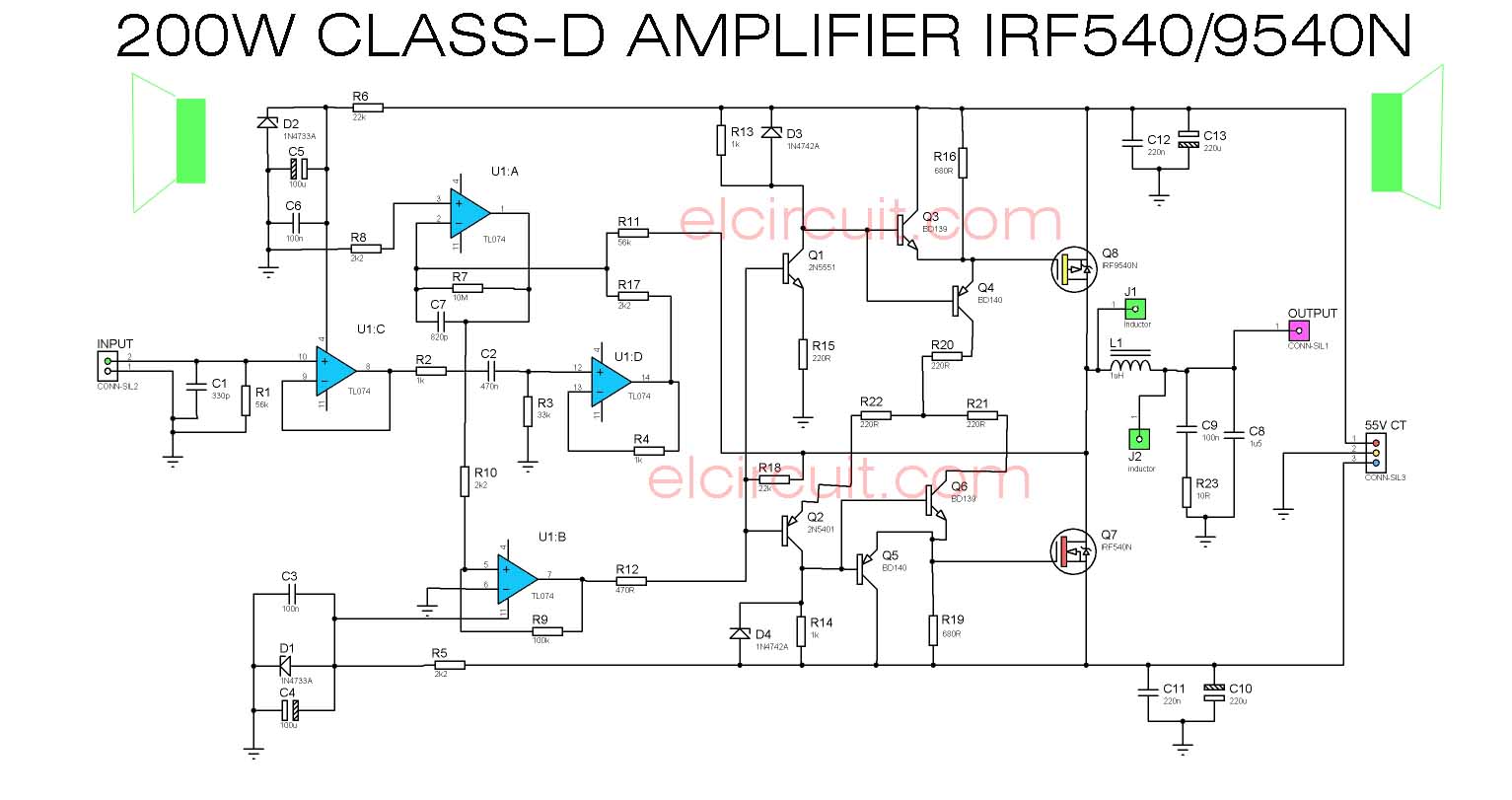
The 1000W class D amplifier circuit diagram is fairly easy to understand. It consists of two main components, the power amplifier and the output filter. The power amplifier is responsible for increasing the signal strength of the input signal before sending it out to the speakers. The output filter then cleans up any distortion caused by the.

TL494 CLASS D AMPLIFIER SMPS CIRCUIT
Class D Power Amplifiers - Circuit Diagram, Operation and Applications: Historically, audio amplifiers have been configured as class A, class B or class AB and the art of design is well known. Also well known is the poor efficiency of these amplifiers compared to that of class D amplifiers.

Class D Amplifier Circuit Using IC 555 Circuit Diagram Centre
Block Diagram The class d amplifier block diagram is shown below. The class D amplifier is a switching amplifier because as compared to different amplifiers like class A, B, and AB, the class D amplifier can reach up to 90-95% of efficiency. Class D Type Amplifier Block Diagram
Class D Amplifier Circuit Diagram
Below you can see the block diagram of a basic PWM Class-D amplifier, just like the one that we are building. The input signal is converted into a pulse width modulated, rectangular signal using a comparator. This basically means that the input is encoded into the duty cycle of the rectangular pulses.

2X400W CLASS D AMPLIFIER DEVICE IR2110
Class C amplifier is tuned amplifier which works in two different operating modes, tuned or untuned. The efficiency of Class C amplifier is much more than the A, B, and AB. Maximum 80% efficiency can be achieved in radio frequency related operations. Class C amplifier uses less than 180-degree conduction angle.

10100W ClassD Power Audio Amplifier Using MD7120 MOSFET Driver Amplifier Circuit Design
Circuit diagram. Class D amplifier circuit BD5460 Notes. The power supply voltage can be between 2.5 to 6.5V DC. For the circuit shown here, the supply voltage must be 3.6 V DC. Powering the circuit from a battery is the better option because it reduces noise. If you are using a DC power supply, then it must be well regulated and filtered.
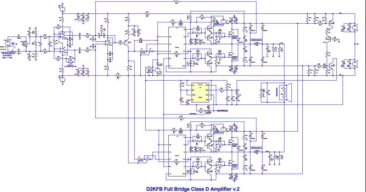
Power Amplifier ClassD Fullbridge D2K 2000Watts Electronic Circuit
A class-D amplifier or switching amplifier is an electronic amplifier in which the amplifying devices (transistors, usually MOSFETs) operate as electronic switches, and not as linear gain devices as in other amplifiers.
Diy high power class d amplifier circuit
The class D amplifier circuit non-linear switching amplifier device. This means, that the amplifier has a conduction angle of 0 degrees because of its switching capability. This amplifier circuit can be more efficient than linear amplifiers. And, it has an efficiency of f 90-95%%. Buy Now Hardware Components

How to Build a ClassD Power Amp Projects
What is a Class-D audio amplifier? The simplest answer will be, it's a switching amplifier. But in order to understand its working, we need to learn how it functions and how the switching signal is produced, for that, you can follow the block diagram given below. So why a switching amplifier? The obvious answer to this question is Efficiency.
Diy Class D Amplifier Schematic
A typical Class D power amplifier consists of a sawtooth waveform generator, comparator (based on an OPAMP), switching circuit, and a low pass filter. The block diagram of a Class D amplifier is shown in the figure below. Sawtooth waveform generator.

classd power audio amplifier circuit based TDA8929T Schematic Design
Class D Amplifier PVDD = 5.6 V to 18 V 3.3 V Second-Order LC Filter Four-Channel BTL Analog Output First-Order RC Filter Four Audio Analog Input Block Diagram www.ti.com 3 Block Diagram Figure 2. Automotive, Four-Channel, Class D Amplifier for Head Unit 3.1 Highlighted Products The TIDA-00573 design uses the following TI products:

TPA3122D2 Class D Audio Amplifier
A class D amplifier operates by deriving a two-state signal from a continuous control signal and amplifying it using power switches. At the core of every class D amplifier is at least one comparator and one switching power stage. In all but the lowest-cost power amplifiers, a passive LC filter is added. Class-D Vs. Class AB Amplifier Comparison.
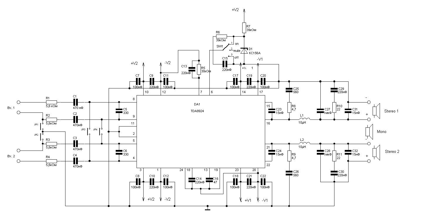
240W Class D Audio Amplifier based TDA8924 Amplifier Circuit Design
The amplifier will only consume power during the on/off transitions if leakage currents are not taken into account. Class D amplifier consisting of the following stages: PMW modulator; Switching circuit; Output lowpass filter; Block Diagram of Class D Amplifier PMW Modulator. We need a circuit building block known as a comparator.

HiFi ClassD Discrete Power Amplifier Electronic Circuit
Let's see the circuit diagram of class D amplifier. Circuit diagram of class D amplifier. To build this amplifier we need to generate a triangular waveform. For this we will use operational amplifiers. Then we need a comparator to compare the triangular waveform and audio signal. Then we need a NOT gate to invert the PWM pulses.

Circuit Diagram Of Class D Amplifier Circuit Diagram
This simplified functional block diagram illustrates a basic half-bridge Class D amplifier. Figure 2. The output-signal pulse widths vary proportionally with the input-signal magnitude. In order to extract the amplified audio signal from this PWM waveform, the output of the Class D amplifier is fed to a lowpass filter.